 |
||||||
Treadles and Teeter-Totters
Different arrangements to provide the downstroke were tried out in the early days before steam power became common as a prime-mover. The bit had to forcibly hit the rock. Leg power on a spring pole was only as reliable as the strength and endurance of the man. Therefore, devices to replace sore legs were put into use, but most of these look rather pathetic although they worked and even became rather elaborate by the 1870's, especially the horse-powered machines.
A walking horse, doomed to spend its shift trodding but going nowhere, provided power. The treadmill ran like an exercise machine. A horse and treadle arrangement served to operate a walking beam rig and could have done the same with a spring-pole. It was a matter of hooking it up right. This means of drilling goes back to the salt days and, after a fashion, even before then.
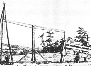 |
This horsepowered treadle is rigged to a wooden walking beam rather than a spring pole. This arrangement was in use in the early salt days and also served for drilling shallow water wells. This cable tool rig is considered portable. Ca. 1810. |
In 1872, a more sophisicated cable-tool device called a horse-driven spudder rig was patented. It used a horse on a treadle but didn't require a spring-pole or permanent walking beam and was considered to be portable. The horse activated a heavy fly wheel, cam, pendulum bar, elbow lever and other apparatus which combined to pull the drilling tools and then allowed them to drop to the bottom.
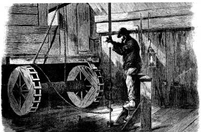
A type of foot treadle used in early oil drilling provided the means to spool hoisted cable on a drum shaft. The device could be called treadle rim bull wheels. Each wooden wheel (one on either side of the shaft) consisted of two rims about ten inches apart. The treadles were rungs of strong wood nailed or screwed to the rims about eight inches apart and were installed entirely around each wheel. This arrangement has been described as a circular ladder (Brantly, 1971). By using his foot on the rungs, the driller could turn the wheels and shaft and thereby wind the manila line or cable on the shaft. He could also control the lowering of the line, especially if a brake device were installed.
|
||
|
In 1861 Andrew Carnegie on his first trip to the oilfields in Oil Creek Valley was fascinated by the strange sights and feverish oil activity there. He wrote vividly about the occasion in his autobiography and thought it fit to mention that he saw two men working their treadles boring for oil upon the banks of the stream. Carnegie, by the way, was a successful oilman, albeit briefly, before he built iron bridges and went on to make steel.
There isn't much information in the literature on the teeter board as a power source. However, since it produced an up and down motion, it must have been able to pull and release the tools. It was tried out with the spring-pole. Brantly (1971) estimates that a teeter board could have worked the drill rods at 60 to 90 strokes per minute, far more than a stirrup-run spring-pole. However, the stroke length was probably quite short. A patent sketch for a well-designed teeter board outfit hasn't been found by the author.
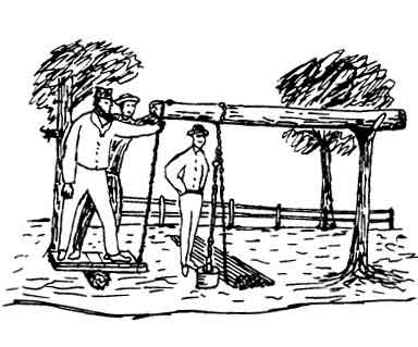 |
The anchored butt end of the spring-pole would be off the drawing to the right. The connecting rope for the teeter board in this example is tied at the working end of the spring-pole instead of behind the tool string. Drilling rods are piled on the ground ready for use. The number of them suggest that this well is programmed to eventually reach close to two hundred feet. This drawing is derived from a drawing believed to represent an early 1800's drilling method. |
![]()
| © 2004, Samuel T. Pees all rights reserved |
|